L'Architectural Institute of Japan (AIJ) ha presentato una serie di noti scenari di riferimento per la simulazione del vento.
Il seguente articolo ruota attorno al "Caso E - un complesso edilizio in un'area urbana reale con una densa concentrazione di edifici bassi nella città di Niigata".
Di seguito, lo scenario descritto è simulato in RWIND2 e i risultati sono confrontati con i risultati simulati e sperimentali dell'AIJ.
Das Architectural Institute of Japan (AIJ) ha una revisione del benchmark Benchmark-Szenarien für Windsimulation vorgestellt.
Der Nachfolgende Beitrag dreht sich dabei um den "Caso A - grattacielo con forma 2:1:1".
Im Folgenden wird das beschriebene Szenario in RWIND2 nachgebildet und die Ergebnisse mit den simulierten und der experimentellen Resultate des AIJ verglichen.
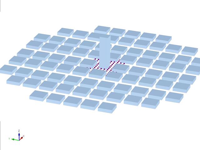
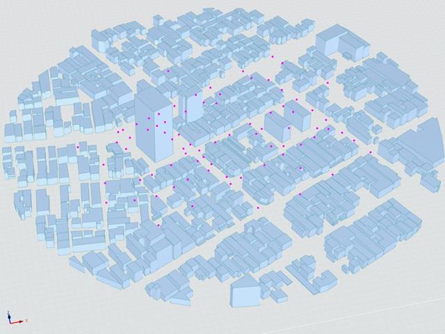
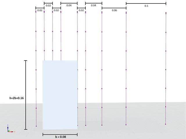
L'Architectural Institute of Japan (AIJ) ha presentato una serie di noti scenari di riferimento per la simulazione del vento.
Il seguente articolo si occupa del "Caso D - Grattacielo tra isolati".
Di seguito, lo scenario descritto è simulato in RWIND2 e i risultati sono confrontati con i risultati simulati e sperimentali dell'AIJ.
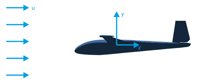
L'obiettivo di questo esempio di verifica è analizzare il flusso del fluido attorno all'aliante. Il compito è determinare il coefficiente di resistenza e il coefficiente di portanza rispetto all'angolo di attacco. Questi coefficienti possono anche essere disegnati nel grafico della resistenza polare. L'angolo limite per il flusso di fluido laminare attorno al profilo dell'ala può anche essere determinato dal campo di velocità. Il modello CAD 3D disponibile (file STL) è utilizzato in RWIND 2.
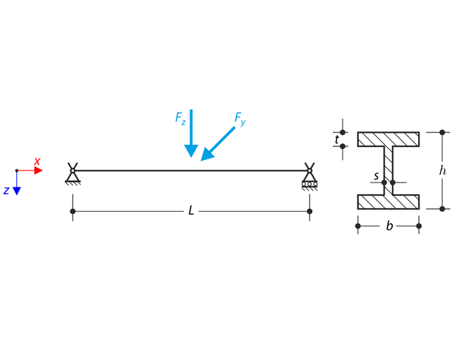
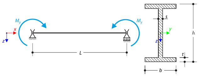
Una struttura costituita da un profilo a I è incorporata nei supporti delle forche. The axial rotation is restricted on both ends while warping is enabled. The structure is loaded by two transverse forces in the middle. The verification example is based on the example introduced by Gensichen and Lumpe.
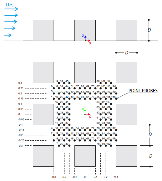
L'esempio di verifica descrive i carichi del vento in diverse direzioni del vento su un modello di un gruppo di edifici. The model consists of eight cubes. The velocity fields obtained by the RWIND simulation are compared with the measured values from the experiment. The experimental data are measured using a thermistor anemometer in the wind tunnel.
Questo esempio di verifica confronta i calcoli del carico del vento su un edificio con copertura a due falde utilizzando la norma ASCE 7-16 e utilizzando la simulazione CFD in RWIND Simulation. The building is defined according to the sketch and the inflow velocity profile taken from the ASCE 7-16 standard.
Questo esempio di verifica confronta i calcoli del carico del vento su un edificio con copertura piana utilizzando la norma ASCE 7-16 e utilizzando la simulazione CFD in RWIND Simulation. The building is defined according to the sketch and the inflow velocity profile taken from the ASCE 7-16 standard.
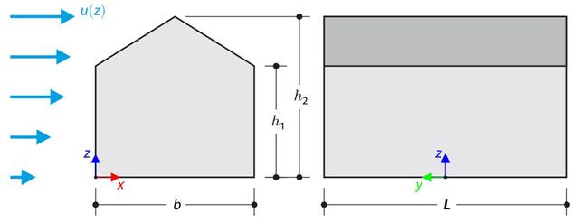
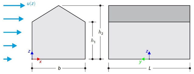
L'esempio di verifica confronta il calcolo del carico del vento su un edificio con una copertura a due falde utilizzando la norma EN 1991-1-4 e utilizzando la simulazione CFD in RWIND Simulation. The building is defined according to the sketch, and the inflow velocity profile is taken according to the standard EN 1991-1-4.
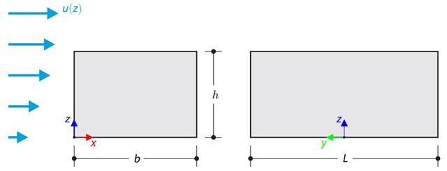
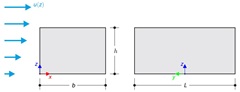
L'esempio di verifica confronta il calcolo del carico del vento su un edificio con una copertura piana utilizzando la norma EN 1991-1-4 e utilizzando la simulazione CFD in RWIND Simulation. The building is defined according to the sketch, and the inflow velocity profile is taken according to the standard EN 1991-1-4.
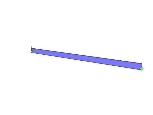
Una trave semplicemente vincolata è caricata per flessione pura. Determine the critical load and corresponding load factor due to lateral buckling.
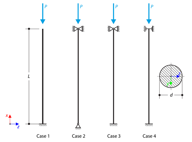
Un puntone con una sezione trasversale circolare è supportato secondo quattro casi base di instabilità di Eulero e soggetto a forza di pressione. Determine the critical load.
Questo esempio di verifica si basa sull'esempio di verifica 0122. A single-mass system without damping is subjected to an axial loading force. An ideal elastic-plastic material with characteristics is assumed. Determine the time course of the end-point deflection, velocity, and acceleration.
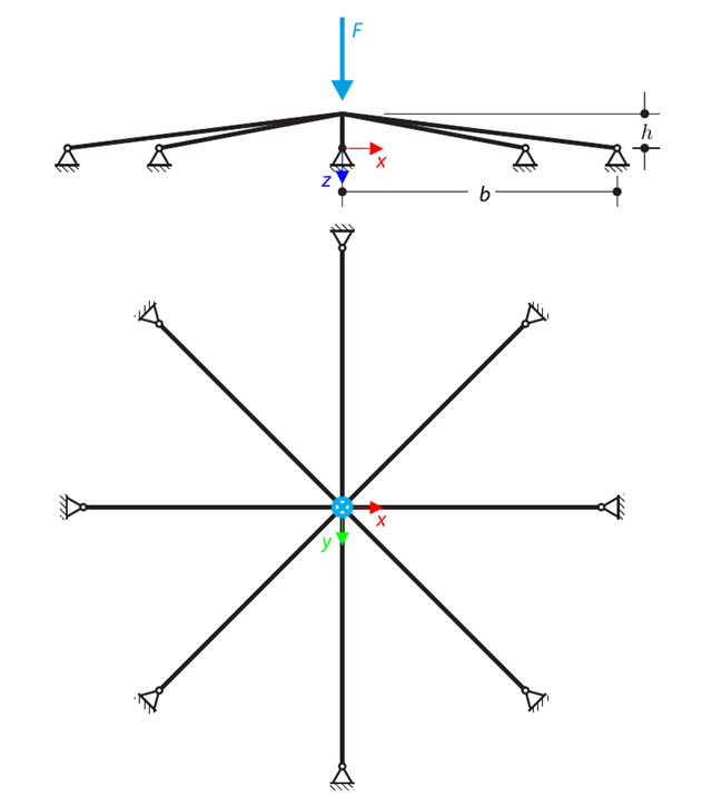
Una struttura poco profonda simmetrica è composta da otto aste reticolari uguali, che sono incorporate nei supporti delle cerniere. The structure is loaded by a concentrated force and alternatively by imposed nodal deformation over the critical limit point when the snap-through occurs. Imposed nodal deformation is used in RFEM 5 and RSTAB 8 to obtain the full equilibrium path of the snap-through. The self-weight is neglected in this example. Determine the relationship between the actual loading force and the deflection, considering large deformation analysis. Evaluate the load factor at the given deflections.
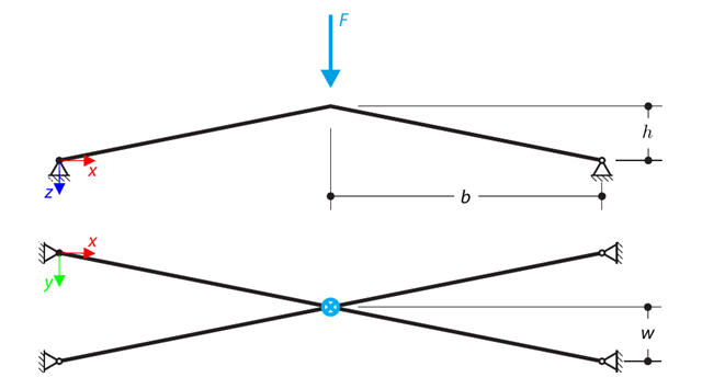
Una struttura è composta da quattro aste reticolari, che sono incastonate nei vincoli esterni delle cerniere. The structure is loaded by a concentrated force and alternatively by imposed nodal deformation over the critical limit point, when snap-through occurs. Imposed nodal deformation is used in RFEM 5 and RSTAB 8 to obtain the full equilibrium path of the snap-through. The self-weight is neglected in this example. Determine the relationship between the actual loading force and the deflection, considering large deformation analysis. Evaluate the load factor at given deflections.
Considera una trave ASTM A992 W 18×50 per campata e carichi permanenti e permanenti uniformi come mostrato nella Figura 1. The member is limited to a maximum nominal depth of 18 inches. The live load deflection is limited to L/360. The beam is simply supported and continuously braced. Verify the available flexural strength of the selected beam, based on LRFD and ASD.
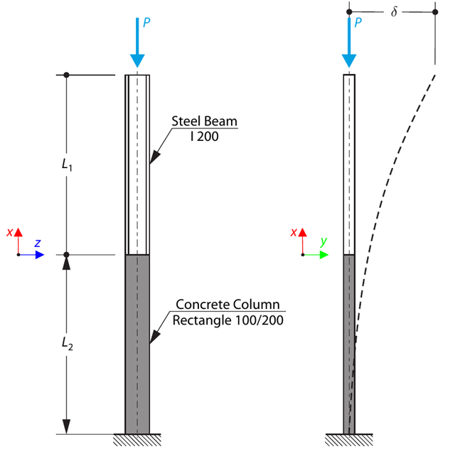
Una colonna è composta da una sezione in calcestruzzo (rettangolo 100/200) e una sezione in acciaio (profilo I 200). It is subjected to pressure force. Determine the critical load and corresponding load factor. The theoretical solution is based on the buckling of a simple beam. In this case, two regions have to be taken into account due to different moments of inertia and material properties.
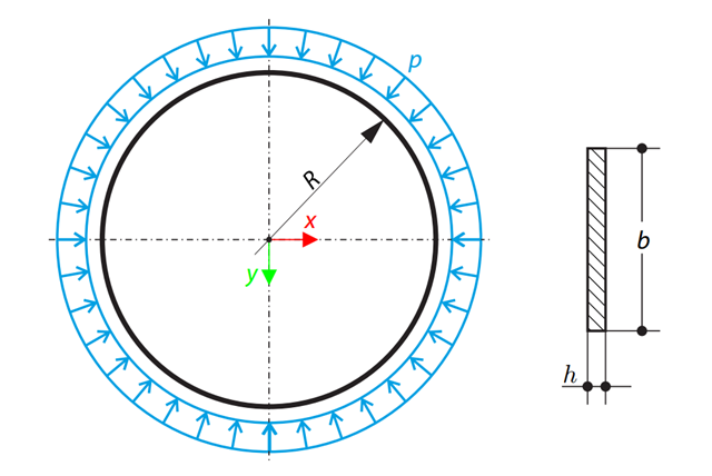
Un sottile anello circolare di sezione trasversale rettangolare è esposto a pressione esterna. Determine the critical load and corresponding load factor for in-plane buckling.
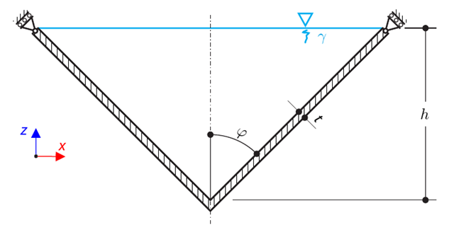
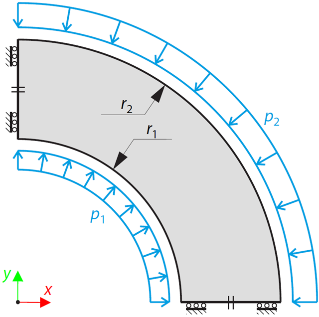
Una trave curva è costituita da due travi a sezione rettangolare. The horizontal beam is loaded by distributed loading. While neglecting self-weight, determine the maximum stress on the top surface of the horizontal beam.
Un recipiente conico a parete sottile è riempito d'acqua. Thus, it is loaded by hydrostatic pressure. While neglecting self-weight, determine the stresses in the surface line and circumferential direction. The analytical solution is based on the theory of thin-walled vessels. This theory was introduced in Verification Example 0084.
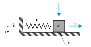
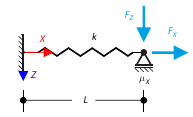
Un oscillatore semplice è costituito dalla massa m (considerata solo nella direzione x) e dalla molla lineare di rigidezza k. The mass is embedded on a surface with Coulomb friction and is loaded by constant-in-time axial and transverse forces.
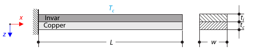
Una striscia bimetallica è composta da invar e rame. The left end of the bimetallic strip is fixed, and the right end is free, loaded by temperature difference. While neglecting self-weight, determine the deflection of the bimetallic strip (free end).
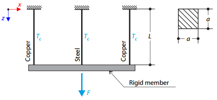
Una struttura reticolare è costituita da tre aste (una in acciaio e due in rame) unite da un'asta rigida. The structure is loaded by a concentrated force and a temperature difference. While neglecting self‑weight, determine the total deflection of the structure.
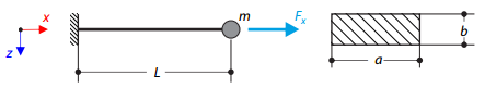
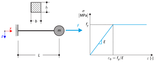
Uno sbalzo di sezione trasversale rettangolare ha una massa alla fine. Furthermore, it is loaded by an axial force. Calculate the natural frequency of the structure. Neglect the self‑weight of the cantilever and consider the influence of the axial force for the stiffness modification.
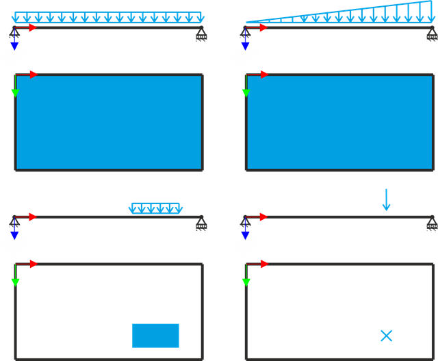
Una piastra rettangolare semplicemente supportata è soggetta a diversi tipi di carico. Assuming only the small deformation theory and neglecting self-weight, determine the deflection at its centroid for each load type.
Questo esempio è una modifica dell'esempio di verifica 0061; l'unica differenza è che il materiale della nave è incomprimibile. An open‑ended, thick‑walled vessel is loaded by both inner and outer pressure. While neglecting self‑weight, the radial deflection of the inner and the outer radius is determined.
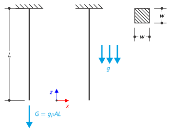
Un'asta con una sezione trasversale quadrata è fissata all'estremità superiore. The rod is loaded by self-weight. For comparison, the example is also modeled with the concentrated force load, the value of which is equal to the gravity. The aim of this verification example is to show the difference between these types of loading, although the total loading force is equal.
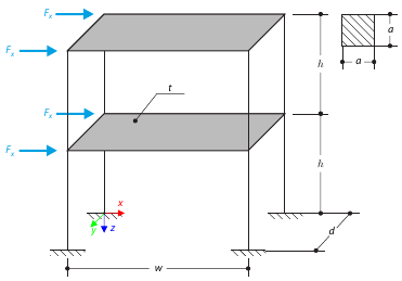
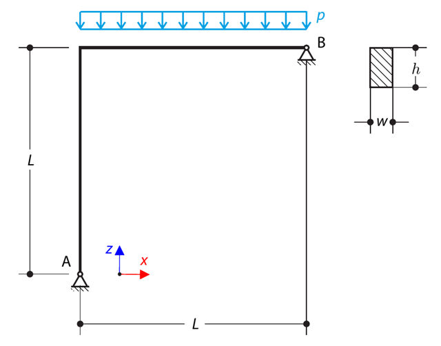
Questo esempio serve come dimostrazione del vincolo del diaframma. The application is shown on a two-story structure. The structure is loaded by means of lateral forces according to Figure 1. Determine the maximum deflection of the structure ux in the direction of the loading forces using both the diaphragm constraint and the plate model of the floor.
L'obiettivo di questo esempio è quello di dimostrare un processo irreversibile causato dall'attrito. After the loading and unloading, the end-point is in a different position than where it was at the beginning. Determine the movement of the node in the X direction.
A structure is made of two trusses of unequal length, which are embedded into the hinge supports. The structure is loaded by concentrated force. Il peso proprio è trascurato. Determine the relationship between the loading force and the deflection, considering large deformations.